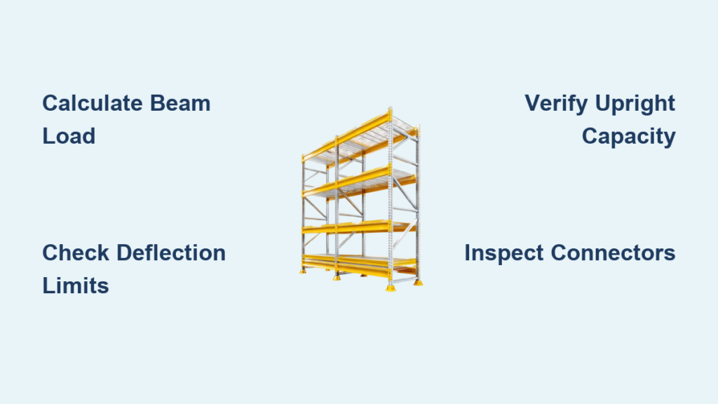
Overloaded pallet racks don’t collapse gradually—they fail without warning, endangering workers, destroying inventory, and creating serious compliance violations. Knowing how to determine rack capacity is a fundamental safety requirement for any warehouse or distribution center. This guide walks you through the complete evaluation process, from calculating beam load limits to checking upright frame capacity and verifying anchor adequacy. You’ll learn the exact formulas, industry standards, and inspection criteria that keep rack systems safe and code-compliant.
Calculate Required Beam Load

Before selecting beams or evaluating your existing system, determine the actual load your beams must support.
Multiply Pallet Weight by Number of Pallets
Each beam pair must handle the total weight of all pallets placed on that level. Use this formula:
Required Beam Capacity = Pallet Weight × Number of Pallets per Level
For example: 2 pallets weighing 2,500 lbs each requires a minimum beam capacity of 5,000 lbs. Remember that capacities are rated per beam pair, not individual beams, and you should always assume weight distributes evenly at 50% per beam.
Apply Load Configuration Multipliers
Not all shelf layouts carry equal stress. Adjust your capacity calculation based on pallet arrangement using these multipliers:
| Pallets per Shelf | Multiplier |
|---|---|
| One pallet | × 0.90 |
| Two side by side | × 1.00 |
| Three wide | × 0.95 |
A beam rated for 5,000 lbs with three pallets wide only safely supports 4,750 lbs after applying the 0.95 multiplier.
Add Impact Load Allowance
Forklift placement creates dynamic forces that must be factored into your capacity calculations. Standard impact allowances range from 12.5% to 25% of pallet weight. Most manufacturer charts include 12.5% impact for two-pallet loads, while high-traffic or corner placements may require the full 25%. Using the example above, a 5,000 lb load with 25% impact becomes 6,250 lb required capacity. Always size beams to handle these peak forces, not just static weight.
Assess Beam Deflection Limits
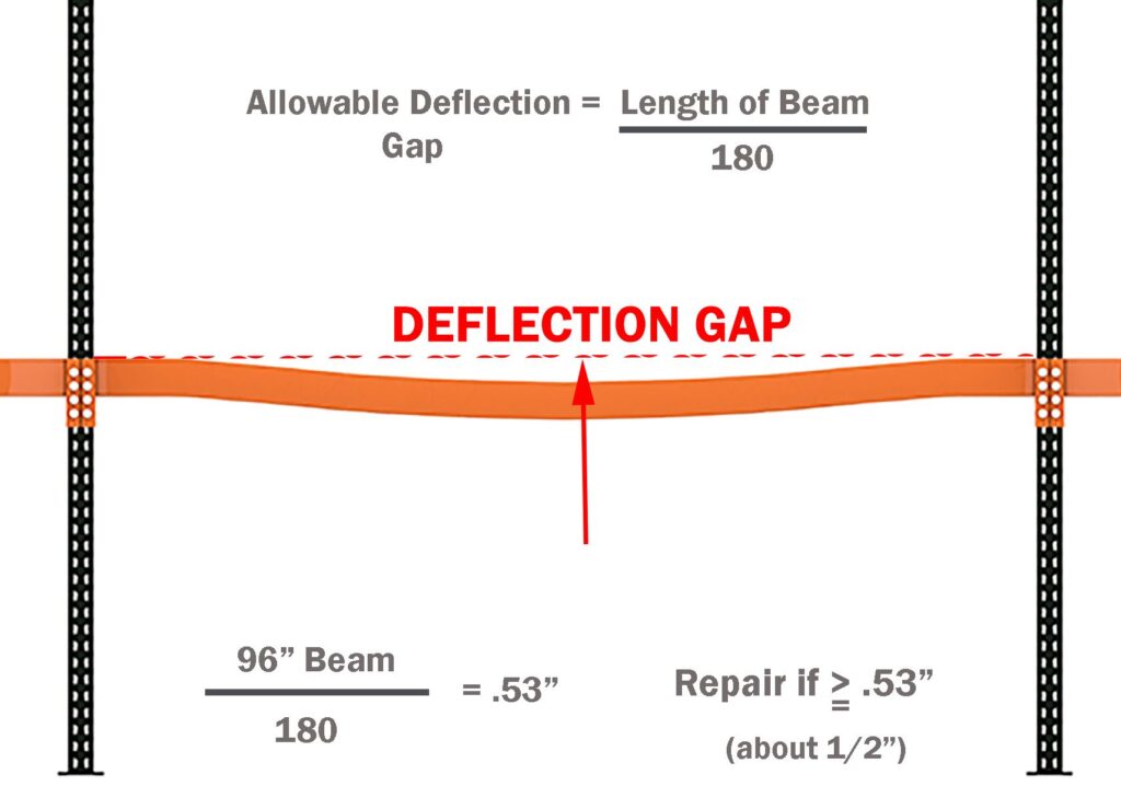
Deflection often serves as the first visible warning sign of overloading and is a key factor in determining beam capacity.
Measure Maximum Allowable Sag
The Rack Manufacturers Institute (RMI) establishes the standard: maximum deflection equals beam length divided by 180. For a 96-inch beam, this calculates to approximately 0.53 inches—about one-half inch. If your beam sags beyond this threshold, it is overloaded or damaged and requires immediate attention.
Identify Visual Warning Signs
Regular inspection helps catch problems before they lead to failure. Watch for these indicators:
- Sagging exceeding one-half inch
- Cracks in welds
- Bent flanges or twisted profiles
- Deformation from forklift impact
Replace any beam showing cracks in weldments or shape deformation caused by impact. Even minor bends significantly reduce structural strength.
Prevent Lateral Instability
Long beams require lateral bracing to resist twisting and maintain stability. Roll-formed beams exceeding 150 inches and structural beams exceeding 108 inches may require lateral ties. These ties stabilize beams under load and prevent progressive collapse.
Identify Beam Specifications When Labels Are Missing

Without manufacturer data, you can estimate capacity from physical measurements.
Measure Key Dimensions
Use a tape measure to record three critical dimensions. Measure beam length from center to center of connectors. Measure beam height from top to bottom of the cross-section, typically 4, 5, or 6 inches. Estimate steel gauge—most beams use 16-gauge steel, while 14-gauge indicates heavier-duty construction.
Estimate Capacity Using Industry Benchmarks
Use these typical capacity ranges when labels are unavailable:
| Beam Height | Typical Capacity Range (per pair) |
|---|---|
| 4 inches | 1,500 – 2,500 lbs |
| 5 inches | 2,500 – 4,000 lbs |
| 6 inches | 4,000 – 6,000 lbs |
When in doubt, use the lower capacity estimate and assume 16-gauge steel until confirmed otherwise.
Confirm with Manufacturer
For certainty, contact the rack manufacturer with beam dimensions and photos. Request written capacity specifications. A manufacturer’s representative can typically measure beam height and provide an accurate estimate based on their product line.
Determine Upright Frame Capacity

The upright column’s strength depends on its weakest vertical span, known as the maximum unsupported span.
Find Maximum Unsupported Span
This measurement represents the tallest open space between two beam levels on a single upright. It directly determines column buckling resistance. For example, if beam levels sit at 48, 96, and 144 inches with 48-inch spans between each, your maximum unsupported span is 48 inches. However, if you remove the middle beam level, creating one 96-inch span, your capacity drops significantly because the system now uses that larger span to calculate load limits.
Sum Total Upright Load
Add all pallet weights supported by one upright column. Each beam level transfers half its load to each upright. Example: Level 1 carries 2,500 lbs (1,250 lbs per upright), Level 2 carries 3,000 lbs (1,500 lbs per upright), and Level 3 carries 2,000 lbs (1,000 lbs per upright), totaling 3,750 lbs per upright. Match this total load and maximum span to the manufacturer’s vertical-spacing chart to select the appropriate upright.
Choose Upright Based on Panel Spacing
Closer beam spacing creates smaller unsupported spans and higher capacity. Wider spacing reduces capacity even if your beams are extremely strong. Always consult the manufacturer’s vertical-spacing chart, which shows allowable loads based on column thickness, steel grade, bracing type, and maximum unsupported span.
Evaluate Connector and Joint Strength
The beam-to-upright connection must transfer full load without failure.
Compare Connector Types
Connector design directly affects system stability and capacity:
| Type | Stability | Capacity Impact |
|---|---|---|
| 3-pin | Standard | Base level capacity |
| 4-pin | Higher | Up to 20% increase |
| Hook-style | Moderate | Varies by design |
| Bolted | Highest | Used in high-load systems |
Using a 4-pin connector instead of a 3-pin can increase beam capacity by up to 20%.
Inspect for Damage and Fit
Check that pins are fully seated, hooks are not bent or cracked, no visible wear or deformation exists, and the beam sits level and secure. Loose or damaged connectors can cause sudden beam dislodgement during normal operation.
Verify Base Plates and Anchors

These components anchor the rack to the floor and resist overturning forces.
Check Base Plate Design
Base plates distribute vertical load to the slab. Key factors include size (such as 6″ × 6″ or 8″ × 8″), thickness, and number of anchor holes. Larger plates reduce ground pressure and prevent sinking into the concrete floor.
Assess Anchor Specifications
Anchors resist uplift during seismic events or forklift impacts. Evaluate diameter (½” or ¾” are common), embedment depth, concrete strength (minimum 2,500 psi typical), and pullout capacity. Anchor capacity must meet ACI 318 standards.
Ensure Seismic Compliance
In seismic zones, anchors must be designed per ACI 318 to handle lateral forces. Inadequate anchors in earthquake-prone regions represent a critical safety failure waiting to happen.
Factor in Environmental Loads
Static weight isn’t the only force acting on your rack system.
Account for Seismic Forces
Earthquake risk varies by location, and seismic loads reduce allowable rack capacity due to lateral shaking, uplift forces, and frame racking. In a seismic zone, capacity depends on frame capacity, baseplate size, anchors, slab thickness, and the specific seismic zone classification.
Include Dynamic Impact Loads
Forklifts generate shock loads during placement that exceed static weight assumptions. Most charts include 12.5% impact, but high-risk areas like corners and narrow aisles require 25%. Design for worst-case impact, not ideal placement conditions.
Use Industry Standards and Tools
Follow recognized codes and leverage modern software for accuracy.
Follow Key Safety Standards
Four standards govern rack design and safety. ANSI/MH16.1 governs rack design including seismic and impact considerations. RMI guidelines set the deflection limit at beam length divided by 180. The AISI Cold-Formed Steel Manual provides structural design basis. OSHA requires that pallet racking support all imposed loads without failure.
Use OneRack for Instant Analysis
OneRack automates capacity calculation by inputting your address, rack height, beam count, and manufacturer. The software outputs local seismic requirements, beam and upright capacities, anchor adequacy, and compliance reports. No engineering degree is required—just input your setup and receive code-compliant results.
Access Manufacturer Charts
Find capacity tables on supplier websites by entering beam length, upright height, beam spacing, and seismic zone. These charts provide exact load ratings for your specific configuration.
Prevent Common Failure Scenarios
Avoid these frequent causes of rack collapse.
Avoid Excessive Unsupported Spans
Removing beams to store taller items creates dangerous unsupported spans. The most common cause of excessive unsupported span is the removal or relocation of horizontal beams. Fix this by installing intermediate beams at the rear to maintain support while preserving front access for forklifts.
Never Mix Components
Using beams or uprights from different manufacturers risks mismatched connectors and unknown capacities. Always use matched, name-brand components designed to work together.
Do Not Reprofile Without Engineering Review
Changing beam levels or adding loads requires engineering validation before proceeding. Even small changes can trigger instability in tall frames. Have a licensed structural engineer review your plans before making modifications.
Take Corrective Actions When Needed
Address capacity issues before they become hazards.
Install Intermediate Beams
Adding beams between existing levels reduces unsupported span at low cost. These can be added to the back side of the rack to maintain front access while restoring upright stability.
Reinforce Uprights
Use boxed columns or column backers to boost strength. These reinforcements slip over or inside existing uprights, increasing buckling resistance and extending the life of existing racks.
Redesign the System
When upgrades aren’t sufficient, consider replacing with higher-capacity racks, adjusting layout for balanced loading, or using taller uprights to accommodate future growth.
Frequently Asked Questions About How to Determine Rack Capacity
What is the formula for calculating beam capacity?
The basic formula is Required Beam Capacity equals Pallet Weight multiplied by Number of Pallets per Level. You must then apply configuration multipliers (0.90 for single pallet, 0.95 for three-wide) and add impact allowance (12.5% to 25%) to arrive at your final capacity requirement.
How do I measure beam deflection to check for overload?
Measure the sag at the center of the beam. The maximum allowable deflection equals beam length divided by 180. For a 96-inch beam, this means 0.53 inches maximum. Anything exceeding one-half inch indicates overload or damage requiring immediate attention.
What is maximum unsupported span and why does it matter?
Maximum unsupported span is the largest vertical distance between two adjacent beam levels on a single upright. This measurement determines upright column capacity because the entire frame’s load rating is based on this weakest vertical span. Removing beam levels dramatically increases this span and reduces capacity.
How do seismic zones affect rack capacity?
Seismic zones introduce lateral forces, uplift loads, and twisting motions that reduce allowable rack capacity. In zones 2 through 5, anchors must be designed per ACI 318 to resist these forces. Always factor in local seismic requirements when calculating capacity.
Can I use beams from different manufacturers in the same rack?
No. Mixing components from different manufacturers risks mismatched connector geometries and unknown capacity ratings. Always use matched components from a single manufacturer to ensure structural integrity and maintain warranty coverage.
What tools help calculate rack capacity automatically?
OneRack software provides instant capacity analysis by inputting your project address and rack configuration. It automatically determines seismic requirements, beam and upright capacities, connector performance, and anchor adequacy while generating OSHA-compliant reports.
Key Takeaways for Determining Rack Capacity
Determining rack capacity requires evaluating every component in the system, not just the beams. Start by calculating required load per level using pallet weight, quantity, configuration multipliers, and impact allowance. Then assess beam strength against deflection limits, verify upright capacity using maximum unsupported span, check connector integrity, and confirm anchor adequacy for your seismic zone. Use manufacturer charts or tools like OneRack for precise calculations rather than guessing. Never modify racks without engineering review, and conduct regular inspections to catch warning signs early. Overloaded racks fail silently and catastrophically—protect your people, product, and compliance by knowing the true capacity of every rack system in your facility.